

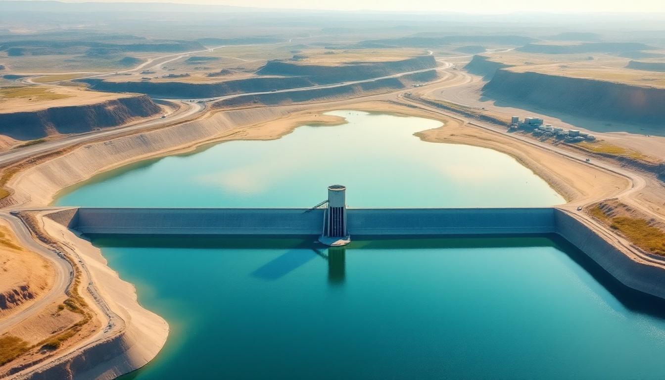
 Settling Pond · Sizing & Routing
Engineered settling ponds, in minutes.
Stokes · Hazen · NRCS · Modified-Puls · server-side math
Geometry
Volume budget
Settling (Stokes)
Hydraulics
Outlet
Cleanout
Storm routing
Dam-safety class (CDA)
Climate scenario applied
Standard applied
Plan view — bottom + top footprint
Cross section — live storm event replay
Pond stack-up
Storm hydrograph — NRCS triangular Qp at design event
Storm inputs / outputs
How to use the 3D view
Click + drag to orbit. Right-click drag to pan. Scroll to zoom. The pond geometry, water level, sediment depth, riser tower and outlet barrel
are all rebuilt from the current server-side compute — change inputs in the sidebar, hit Compute design, then come back to this tab.
Run storm replays the design hydrograph in real-time: the water surface rises into the surcharge zone, the riser starts spilling,
the outlet barrel discharges, and the surface drops back as the pond drains. Rain adds storm particles for atmosphere.
Vendor RFQ Package
1. Pond geometry
| Bottom dimensions (L × W) | — |
| Top dimensions (L × W) | — |
| Operating depth | — |
| Freeboard | — |
| Embankment height | — |
| Side slope H : V | — |
| Total impoundment volume | — |
2. Earthworks
| Excavation volume (in-situ) | — |
| Embankment fill | — |
| Net earth balance | — |
3. Liner system
| Wetted area (bottom + slopes) | — |
| Recommended liner | 1.5 mm HDPE or 6 mm GCL · supplier choice · lap allowance per supplier spec |
4. Principal spillway
| Riser — diameter | — |
| Riser — concrete | — |
| Barrel — diameter | — |
| Barrel — length | — |
| Barrel — concrete | — |
| Rebar (est.) | — |
5. Emergency spillway
| Bottom width × depth | — |
| Capacity | — |
| Lining | — |
| Riprap / concrete volume | — |
6. Hydrology & design criteria
| Design standard | — |
| Climate scenario | — |
| Design storm | — |
| Peak inflow | — |
| Required detention | — |
| CDA consequence class | — |
7. Notes & disclaimers
Quantities are screening-grade (±25% typical) intended only to support vendor quotation and constructibility review. Engineer-of-record stamping is required before construction. Liner, geotextile, rebar and concrete schedules must be detailed by the design engineer. Beedy Inc. carries no liability for quantities used outside that scope.
Server-side math
1. Settling — Stokes
Discrete-particle quiescent settling for the design particle (Stokes regime, Re < 1):
Water density and dynamic viscosity μ(T) follow IAPWS-style fits as functions of pond temperature.
Required surface area is set by the overflow-rate criterion A_s = Q / v_s (Hazen 1904).
Metcalf & Eddy 5e §5-4; Crittenden MWH Water Treatment 3e §6-4.
2. Geometry & volume
Given the required surface area, length and width are derived from the target L:W ratio per the selected standard. Top dimensions account for the side slope H:V trapezoidal cut:
Total impoundment volume is computed by the prismoidal rule across sediment, active, storm and freeboard zones.
3. Hydrology — NRCS / SCS
Time of concentration uses Kirpich (default), SCS Lag, or a manual override:
Direct-runoff depth uses the SCS curve-number method:
The NRCS triangular unit hydrograph gives peak flow:
USDA-NRCS NEH Part 630; ASCE Manual 77 §5; Chow, Maidment & Mays §15.
4. Outlet sizing
Principal spillway is a riser-barrel combo. Riser size is set by the orifice-controlled drawdown of the active storage to the target drawdown time. Barrel is checked against inlet-control and pressure-flow regimes. Emergency spillway is a broad-crested grass / riprap / concrete channel with Manning's n by lining type.
USDA-NRCS TR-60 Earth Dams & Reservoirs; FAO Irrigation & Drainage Paper 26.
5. Storm routing — Modified Puls
Storage-Indication routing (Modified Puls) propagates the design hydrograph through the pond + outlet system in dt steps, returning peak stage, outflow, attenuation and volume-balance error.
Chow, Maidment & Mays §8-3; USACE EM 1110-2-1417.
6. Sediment budget
Annual sediment load is derived from TSS removal at the continuous design flow plus the storm event captured during the cleanout period. Volume is back-calculated using the user-supplied settled bulk density (default 1300 kg/m³, typical for mining tailings sand).
7. Design standards
BC G7 — British Columbia Mines Act Technical Guidance 7. Conservative; 48-hr detention,
10-yr 24-hr storm, sediment-load-based cleanout sizing.
USEPA — 40 CFR 434 baseline for coal/metal mine sediment ponds.
Alaska Placer — ADEC alluvial-placer adapted with coarser d50 defaults.
Custom — supply your own detention target, L:W, depth, freeboard, side slope and short-circuit factor.
References
Hazen, A. (1904). On Sedimentation. Trans. ASCE 53, 45–88.
Stokes, G.G. (1851). On the effect of internal friction of fluids on the motion of pendulums.
USDA-NRCS (2010). National Engineering Handbook, Part 630 — Hydrology.
ASCE (1992). Manual 77 — Design and Construction of Urban Stormwater Management Systems.
Chow, V.T., Maidment, D.R., Mays, L.W. (1988). Applied Hydrology. McGraw-Hill.
Crittenden et al. (2012). MWH Water Treatment: Principles and Design, 3rd ed. Wiley.
Metcalf & Eddy / AECOM (2014). Wastewater Engineering, 5th ed. McGraw-Hill.
USACE (1994). EM 1110-2-1417 Flood-Runoff Analysis.
BC MEM (2016). Technical Guidance Document 7 — Mine Sediment Pond Design.
USEPA (2014). 40 CFR Part 434 — Coal Mining Point Source Category.
© Beedy Inc. 2026 · Math executes server-side on a Beedy FastAPI service. Outputs are sizing aids and require engineer-of-record review and stamping before construction. Beedy Inc. carries no liability for results used outside this scope.